44 labelled diagram of bunsen burner
1. Introduction to chemistry Questions and Answers - EcoleBooks 1. Wooden splints F and G were placed in different zones of a Bunsen burner flame. (b) Name the type of flame that was used in the above experiment. 2. The diagrams below represent a list of apparatus which are commonly used in a chemistry laboratory:-. (a) Give the correct order of the apparatus, using the letters only, to show the correct ... Labelling a Bunsen Burner - Labelled diagram - Wordwall Labelling a Bunsen Burner - Labelled diagram Collar, Base, Gas Valve, Chimney, Flame (Inner Cone), Rubber Tubing, Flame (Outer Cone), Air Hole, Heat Proof Surface. Labelling a Bunsen Burner Share by Shonprebble KS3 Y7 Science Working scientifically Like Edit Content More Leaderboard Log in required Theme Log in required Options Switch template
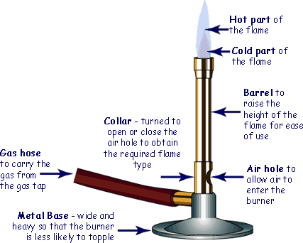
Labelled diagram of a Bunsen burner - Quizlet chimney or barrel raises the height of the flame for easy use air hole to adjust the flame from a luminous flame to a non-luminous flame and allow mixing of gases (combustion) rubber tubing carries the gas to the burner from the gas tap on the laboratory bench. base This is to prevent it from falling, which would burn your desk. heat proof mat

Labelled diagram of bunsen burner
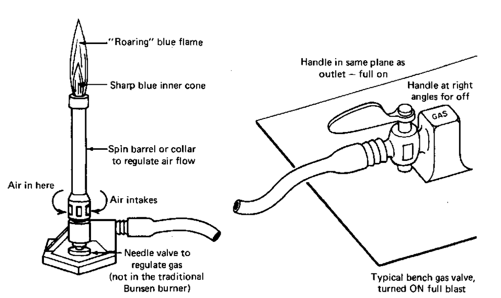
6. Label the given diagram of Bunsen burner with the phrases given ... Refer figure with Labelled Diagram Explanation: How to use Bunsen Burner- 1.) Check if there is any holes/breaks. 2.) Hose is connected to gas tap. 3.) Air holes are closed & checked. 4.) Splint is lighted up and placed above nozzle. 5.) Gas Tap is turned on. 6.) Yellow flame comes from the Bunsen. 7.) Bunsen Burner Basics - Flinn Sci 4 21 inn cieniic nc is esere Name: _____ Bunsen Burner Quiz 1. Label the parts of the Bunsen burner. 2. Draw a diagram of a correct Bunsen burner flame and label the hottest spot. Bunsen burner | Definition, Description, & Facts | Britannica The Bunsen burner consists of a metal tube on a base with a gas inlet at the lower end of the tube, which may have an adjusting valve; openings in the sides of the tube can be regulated by a collar to admit as much air as desired.
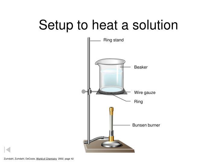
Labelled diagram of bunsen burner. Bunsen Burner Parts and Functions, Diagram - FreeSkill.PK Bunsen Burner Function With Diagram Bunsen burner parts of laboratory mainly used for heating materials. The holder is located under the frame, and there is a glass test tube on the holder. The test tube contains other liquids to heated. Use a mixed gas with a continuous flame. The six main parts are as follows: Bunsen Burner Diagram Example dynamicpapers.com › wp-content › uploads03 0620 62 2RP - IGCSE Past Papers The apparatus was set up as shown in the diagram, ensuring the inverted measuring cylinder was full of water. The bung was removed from the boiling tube. A coiled length of magnesium ribbon was added to the boiling tube, the bung was immediately replaced and a timer started. examafrica.com › 2022-waec-practical-specimen-for2022 WAEC PRACTICAL SPECIMEN FOR MAY/JUNE EXAMINATION May 10, 2022 · (o) Bunsen Burner/source of heat (p) Droppers (3) (a) 150cm3 of iodine solution in a corked flask or bottle labeled ‘An’. These should all be the same containing 25.4g of I2 in 6.0g kl per dm3 of solution. (b) 150cm3 of sodium thiosulphate pentahydrate solution in a corked flask or bottle labeled ‘Bn’. PDF The Bunsen Burner (1) - eChalk The Bunsen burner was placed on a heat resistance surface. The Bunsen burner is not too close to the edge of the desk. The burner was connected to the gas tap correctly. The rubber tubing was checked for cracks or leaks. The air hole on the Bunsen burner was closed before lighting. The splint was lit before the gas was turned on.
Bunsen Burner Poster - Diagram with Labels | Teach Starter A poster containing a diagram with labels showing the key parts of a Bunsen burner. Use this educational classroom poster in your science lessons to highlight the key parts of a Bunsen burner. A lot of equipment is used in science experiments and it is important to know the names of and understand each part of the equipment and how it works. ccea.org.uk › downloads › docseeal efiae ea a - CCEA The boiling tube was placed in a beaker of water and heated using a Bunsen burner. The contents of the boiling tube were stirred using a thermometer. All the potassium iodide dissolved and a saturated solution was obtained at 35°C. (i)Draw a labelled diagram of the assembled apparatus used in this experiment. [3] Bunsen Burner Poster - Diagram with Labels | Teach Starter A poster containing a diagram with labels showing the key parts of a Bunsen burner. In Science it is important that students know how to use a variety of tools when conducting scientific experiments and inquiry. This poster focuses on the Bunsen burner and highlights its key parts. There are two print options available for this poster: How to Draw Bunsen Burner labelled Diagram - YouTube In this video I'm going to Draw Bunsen Burner which is a lab Equipment labelled diagram #bunsenburner #abhishekeducare
Label a bunsen burner Diagram | Quizlet Label a bunsen burner Diagram | Quizlet Label a bunsen burner STUDY Learn Write Test PLAY Match + − Created by SWPSChemistry TEACHER Terms in this set (9) Flame (outer cone) ... Flames (inner cone) ... barrel or chimney ... collar ... base ... rubber tubing ... air hole ... gas valve ... heat proof surface ... THIS SET IS OFTEN IN FOLDERS WITH... Bunsen burner | Definition, Description, & Facts | Britannica The Bunsen burner consists of a metal tube on a base with a gas inlet at the lower end of the tube, which may have an adjusting valve; openings in the sides of the tube can be regulated by a collar to admit as much air as desired. Bunsen Burner Basics - Flinn Sci 4 21 inn cieniic nc is esere Name: _____ Bunsen Burner Quiz 1. Label the parts of the Bunsen burner. 2. Draw a diagram of a correct Bunsen burner flame and label the hottest spot. 6. Label the given diagram of Bunsen burner with the phrases given ... Refer figure with Labelled Diagram Explanation: How to use Bunsen Burner- 1.) Check if there is any holes/breaks. 2.) Hose is connected to gas tap. 3.) Air holes are closed & checked. 4.) Splint is lighted up and placed above nozzle. 5.) Gas Tap is turned on. 6.) Yellow flame comes from the Bunsen. 7.)

Bunsen Burner lineart | Clipart Panda - Free Clipart Images

Bunsen Burner Diagram | Mr Brovont's Science Blog | Bunsen burner ...
Physics revision | GCSE and A Level Physics Revision | Cyberphysics ...
Distillation apparatus - Labelled diagram
Sources of Heat (Laboratory Manual)
PPT - Methods of Separating Mixtures PowerPoint Presentation - ID:2399554
How to Light A Bunsen Burner

Amedelyofpotpourri: Bunsen Burner Parts Labeled
Post a Comment for "44 labelled diagram of bunsen burner"